Highly stable under hydrogen sulfide exposure environment without sulfation or discoloration, with stable battery performance and durability during charging and discharging.
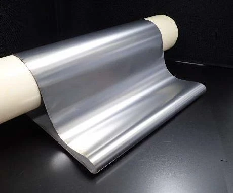
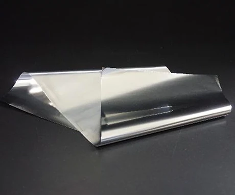
Developed materials (electrolytic iron foil/Fe-Ni alloy foil)
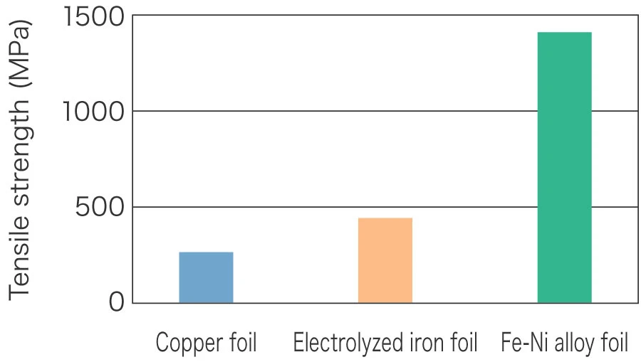
Tensile strength (copper foil vs. ferrous metal foil)
Characteristics
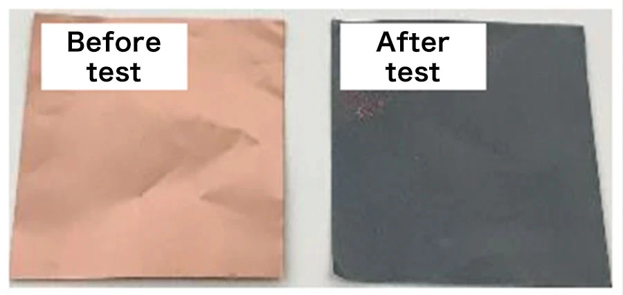
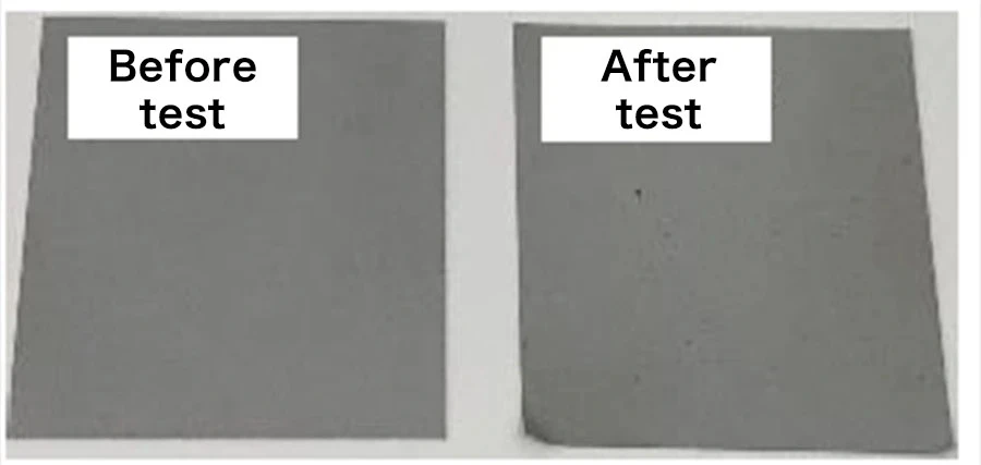
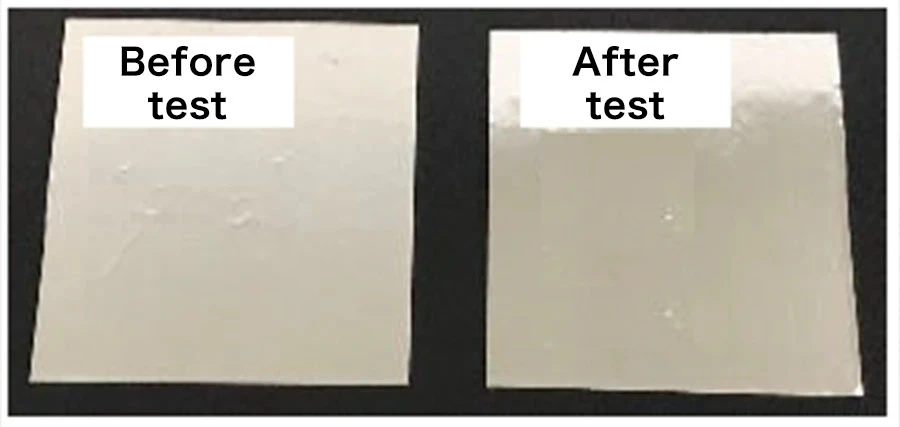
Gas corrosion test (hydrogen sulfide)
Contact resistance ratio: 3.2
Contact resistance ratio: 1.0
Contact resistance ratio: 1.0
This is a before/after test comparison.
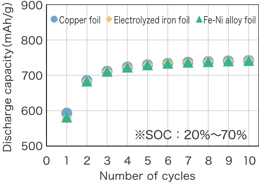
Cycle characteristics of SiO anode using various current collectors
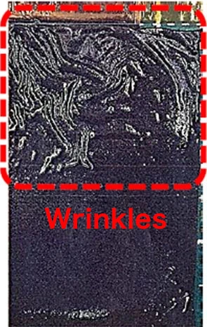
External image of test battery after dismantling
(10µm)

(10µm)

(10µm)
Joint research organization: AIST Battery System